Content
- Introduction
- 1. Description of the research object
- 2. Existing automated control systems, their methods, functions and output goals
- 2.1Automated control system
- 2.2 Automated electrical management system
- 2.3 Automated control system of the gas control point (hydraulic fracturing)
- 4. Architecture and arrangement
- 5. Analysis of existing energy management systems
- Conclusions and improvements in software
- List of sources
Introduction
Modern power supply of industrial enterprises is a complex cybernetic type system characterized by a large number of interconnected elements and subsystems.
The study of such systems is not possible without the use of a sufficiently powerful mathematical apparatus and digital computers. The ever-increasing pace of electrification of the national economy and the energy supply of labor lead to the need for mass design of power supply systems and their development. The volume of this work is so great that a reduction in labor costs for this work becomes absolutely necessary.
This problem can be solved by automating the design of power supply systems, as well as through the use of modern mathematical methods and their software.
1. Description of the research object
A study related to the automation of the enterprise's power supply management system. And since enterprises are different, there will be some common part connecting all enterprises. For example: light control, heating control, ventilation control.
And each enterprise has its own unique one, so the gas supply enterprise will include control of pumps, various sensors that will take readings in real time, and the program should be able to process all this information and take some measures in excitonic cases.
2. Existing automated control systems, their methods, functions and implementation goals
2.1 Automated control system
An automated control system or automated control system is a complex of hardware and software designed to control various processes within a technological process, production, enterprise. Automated control systems are used in various industries, energy, transport, etc.
In order to increase the operational reliability, durability and efficiency of power equipment, to solve the tasks of dispatching, production, technological and organizational and economic management of the energy sector, enterprises can be equipped with automated energy management systems (ASMS).
These systems are subsystems of the automated Enterprise Management System (ASM)and they must have the necessary means of transmitting information from the control rooms of the power supply system to the extent agreed with the latter.
The complexes of ASUE tasks in each energy sector should be selected based on production and economic feasibility, taking into account the rational use of available standard solutions and the capabilities of the operated technical means [1].
Automated electrical management system (ACS SES)It is an integral part of the ASUE and, as a rule, includes dispatching control systems for power supply and repair of electrical installations, distribution and sale of electricity, as well as management systems for industrial and economic processes in the electrical industry.
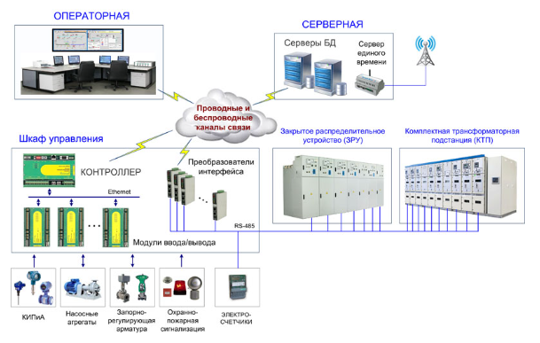
For the control and accounting of energy resources (electricity, heat, water), a special subsystem is included in the ASUE (automated system for monitoring and accounting of energy resources). Separately, the subsystem of heat and water supply of the enterprise in the ASUE should be highlighted (Fig. 1).

Figure 1 – Control diagram
The operator's ARM provides:
- convenient and visual provision of operational information in the form of technological mnemonics, graphs and tables;
- providing an interface for controlling actuators with protection against erroneous actions and unauthorized control;
- output of sound and color alarms during fault diagnosis, output of values of controlled parameters beyond the limits of warning and (or) pre-emergency settings;
- displaying the event log in the system (event log);
- displaying tables and graphs of changes in controlled parameters over time;
- display and printing of reports, statements and other printed documents, copies of displayed video frames, event protocol, etc.
2. Automated electrical management system
The automated electrical management system provides the following functions:
- display of the current state of the main power supply circuit in the form of a mnemonic circuit;
- measurement, control, display and registration of parameters;
- processing and output of information about the status of the main circuit and equipment in text (tabular) and graphical form;
- remote control of switching switches of the main circuit with control of the actions of the attendant;
- processing of steady-state data for various operational purposes;
- diagnostics of protections and automation with alarm;
- remote modification of digital REA settings, control of their commissioning;
- registration and signaling of the occurrence of ferroresonance modes in the network;
- validation of input information;
- equipment diagnostics and control;
- formation of a database, storage and documentation of information (maintenance of a daily statement, a statement of events, archives);
- technical (commercial) accounting of electricity and control of energy consumption;
- control of electricity quality parameters;
- automatic emergency control;
- registration (oscillography) of parameters of emergency and transient processes and analysis of oscillograms;
- monitoring of the battery mode and isolation of its circuits;
- diagnostics of the state of the SES automated control system equipment and software;
- transmission of information about the state of the power supply system to the technological automated control system via its communication channel to the Central data center and other services of the enterprise.
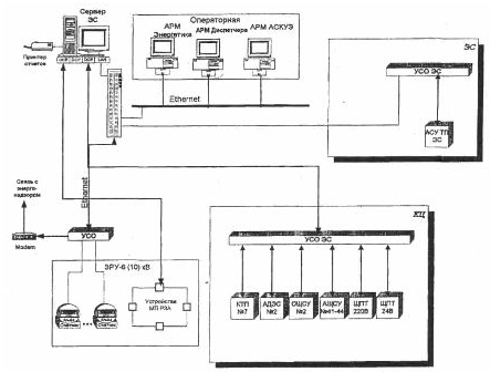
Figure 2 shows the approximate structure of the circuit of the automated control system of the compressor station. The structure of the automated control system of the SES depends on the type of CS (electric or gas turbine), the presence of a power plant for its own needs (ESN) on the CS and on its operating modes. The degree of integration of the ESN into the power supply system (SES) is also important.

Figure 2 – Block diagram of the automated control system of the compressor station
3. Automated control system of a gas control point (hydraulic fracturing)
Gas control points (hydraulic fracturing) designed to reduce gas pressure and maintain it at specified consumption levels of the station.
Implementation goals:
- improving the reliability of technological equipment, reducing the risk of severe accidents so that failures of technical means do not lead to situations dangerous to human life and health and damage to equipment;
- provision of automated effective control of technological processes in normal, transient and emergency modes of gas distribution;
- timely provision of sufficient and reliable information to operational personnel on the progress of the technological process, the condition of equipment and technical controls;
- reducing the cost of operation and repair of automation equipment;
- ensuring commercial accounting of natural gas consumption.
System functions
- Collecting and processing information from temperature, pressure and pressure difference sensors connected to constricting devices, and calculating the volume and mass flow of natural gas in the pipeline.
- Automatic switching of pressure difference measurement ranges to increase the flow measurement range.
- Restoration of accounting parameters after system downtime with addition to their values at the time of shutdown of the product of downtime by a contractual constant or the value of consumption before shutdown.
- Control of the reliability of the received information by boundary values, rate of change and other criteria.
- Receiving discrete information about the condition of the valve, from the keys of the MSHU.
- Ensuring the operation of emergency protection and blocking of equipment in accordance with the requirements of regulatory documents: increasing the gas pressure behind the hydraulic fracturing to the 1st and 2nd limit, lowering the gas pressure behind the hydraulic fracturing, switching the gas reduction line to the "OPERATION" mode, "AVR", "laquo;DISABLED» and the prohibition of valve control from two places.
- Remote control of actuators.
- Calculation of the volume and mass of natural gas that has passed in an hour, day, decade and month through gas pipelines and in general through the metering unit.
- Displaying information to operational personnel on color monitors in the form of mnemonic diagrams with indication of parameters in digital, tabular form or in the form of graphs.
- Formation of light and sound alarms for deviations of parameters from the specified warning and emergency limits, as well as in other emergency situations.
- Display of mnemonic images of electric valves with dynamic indication of their states and the possibility of remote control.
- Manual input of source data in real time.
- Automatic generation, issuance of data to operational personnel and printing of accounting printed documents both automatically and on request.
- Performing transitions «Winter-Summer» and «Summer-Winter».
- Multi-user mode of operation, while using the differentiation of access rights to the system by passwords, registration of a person's access and logging of his actions.
4. Architecture and equipment
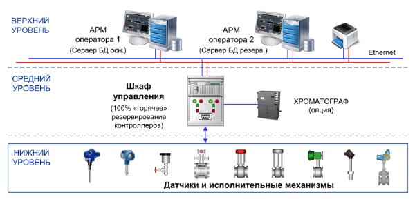
Hydraulic fracturing control system is a two-level distributed system with multi-stage failure protection, providing high reliability [2].
The lower level is represented by modern, highly reliable microprocessor controllers. The controllers are made with 100% "hot" redundancy. The controllers are located in the control and control cabinets.
The upper level is represented by operator workstations (operator/archiving stations-a server with a full graphic project volume, with a 100% hot backup function and archiving functions).
Communication with the lower-level controllers is carried out via a local computer network using a fiber-optic communication line made according to the scheme of 100% "hot" redundancy (Fig.3).

Figure 3 – Architecture and Hardware
5. Analysis of existing energy management systems
There are more such systems and each new and modern version will be an improvement of the old methods and the application of new ones. Let's consider new and popular complexes:
1.ETAR 22 is a comprehensive tool for detailed analysis of alternating and direct current systems [3].
The DC system uses the same database as the AC network. The modules "Steady state in DC systems" and "Calculation of short circuits in DC systems" provide engineers with opportunities for the design and maintenance of DC systems. The module "Determining the parameters of batteries and their discharge" is used to select the most suitable battery cells, check the capacity of existing batteries and simulate various scenarios for the operation of a DC system.
2.ANARES is a software package for calculations, analysis and planning of operating modes of electric power systems [4]; The complex is designed for operational calculations, analysis, planning of operating modes of electric power systems (EES); their management at various territorial levels of dispatching control. The main users of the complex are the dispatch control centers of the system operators of the EES, electric grid enterprises, power generation companies, large industrial organizations, design and engineering organizations in the electric power industry, training centers.
Global is a platform created for the electric power industry, which allows you to optimize work at all stages - generation, sales, consumption, network supply [5]. The solution will automate all tasks for energy supply companies - billing, energy trading, settlement with consumers, heat supply. For generating companies, the system will help to perform energy accounting and consolidation, planning, and work on OREM. Electric grid companies will be able to carry out power supply and technical connection. Energy-consuming companies will be able to increase energy efficiency and plan consumption.
4.ESP. PA is a program for analyzing the operation of emergency automation. Collects and transmits information about the functioning of objects, visualizes the passage of information through the network, signals equipment failure or loss of emergency control [6]
5.IndorPower - implementation of technical specifications, electrical parameters of the subscriber's load and information on consumption. Displaying subscribers on maps and network diagrams [7]. Billing of consumption with a flexible tariff setting system. Displaying power lines on a terrain plan with plans of supports, horizontal dimensions of spans, crossings, intersections, glades and adjacent objects (situations). Displaying plans of substations, equipment, secondary and signal circuits. Diagrams of substations, secondary and signal circuits. Protection schemes and protection setpoint maps. Technical data sheets of all types of power equipment.
Conclusions and improvements in software
The introduction of artificial intelligence into energy management systems will allow us to engrave and offer the system a more optimal work model. Artificial intelligence should also have the rights to manage and make decisions in case of accidents based on the experience of emergency situations that it has been trained in.
The forecasts that the system makes during operation, when displaying them in the form of a graph, you can visually see what happened, whether the load indicators increased or decreased. Forecasts should also be shared for individual nodes with their evaluation.
The expansion of the functionality will allow you to cover most of the managed functions and calculation functions under one system, rather than many that will solve only one of the tasks.
Protection algorithm and system code for emergencies (each code corresponds to its own accident in the system) their coupling under AI control will allow you to resolve the accident very quickly or notify the operator on your smartphone that something has happened. Communication with the smartphone must be local and according to special protocols so that it would be impossible to hack the system from outside [8].
Based on the above proposed improvement or creation of new software, taking these requirements as a basis, it can be assumed that the application should be cross-platform and sharpened for remote control over the network through a special security protocol. As well as a server with large computing capacities for both system analysis and system management AI [9].
The computer version may include extensions to the energy management functionality, but notification of errors or other important notifications and monitoring of the system should also come to the mobile device, which the operator always falsely has at hand from which, according to the situation, he can send a command so that the head of the computer executes it.
A cross-platform project consists of three types of modules:
- General module contains code that is not specific to any particular platform, as well as declarations for implementing platform-dependent APIs. These declarations allow common code to be a dependency for platform-specific implementations.
- The platform module contains platform implementations of dependent ads from a common module for a specific platform and other platform code. A platform module is always an implementation of one common module.
- A regular module. Such modules are based on a specific platform and can either be a dependency of platform modules or depend on them [10].
Thus, this direction towards the development of software complexes in the energy sector has great prospects in the future. But there are also certain difficulties. Electrical engineering and energy are extensive, so the program should be multifunctional. But in order not to complicate the software package too much, it needs to be made modular. Each module is responsible for some area of calculations or modeling.
Therefore, it is better to develop the program in several stages. Starting with minimal functionality at the initial stages of development, then adding new ones provided for by further stages. Without forgetting to divide the program into modules, you can achieve a completely powerful software package. Also, using cross-platform solutions, it is possible to achieve greater distribution of the program with less effort.
List of sources
- A method for developing software and computing complexes for the design of power supply systems [Electronic resource]. – Access mode:https://cyberleninka.ru/article
- Automated control system of the gas control point (hydraulic fracturing) [Electronic resource]. – Access mode:https://www.krug2000.ru/decisions/
- ETAP 22 [Electronic resource]. – Access mode:https://helpcenter.etap.com/portal/
- ANARES software and Computing complex [Electronic resource]. – Access mode:https://rdc-sg.com/download/АНАРЭС%20
- GLOBAL-ENERGY - [Electronic resource]. – Access mode:https://global-system.ru/index
- ESP. PA - [Electronic resource]. – Access mode:https://energosoftpro.ru/programmnye
- IndorPower - [Electronic resource]. – Access mode: https://indorsoft.ru/products/power/
- The technology of building a virtual private network is IPsec and SSL protocols. - [Electronic resource]. – Access mode: https://teacherbox.ru/arhiv/...
- The use of artificial intelligence in the management of power systems - [Electronic resource]. – Access mode: https://scilead.ru/article/...
- EveryCircuit - [Electronic resource]. – Access mode: https://everycircuit.com
